Have you ever sat at your desk, digesting the results of your most recent Simulation study, and wondered: “Is this right?” If you’re like most engineers, the answer is, (and probably should be), yes.
While incorrect Simulation results can be caused by anything from a typo in your pressure load to bogus material properties, by far the most common issue is an inadequate mesh, and the possibility of tricky things called stress singularities. In terms of the mesh, convergence refers to the process where results hone in on trustworthy values, independent of mesh factors that might be distorting the truth.
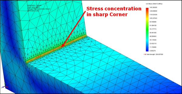
A mesh that is too coarse, where elements are too large around small geometry, will not have the detail necessary to display accurate results- often underestimating the stresses you see. Conversely, stress singularities are a phenomenon inherent to all finite element analysis tools (that is, where a 3D model is broken up into small, easy-to-analyze bits), in which stress values are overestimated. They shoot higher and higher as a user tries to refine the mesh in a sharp corner, never leveling off, or converging. The underlying causes are fairly complex, but suffice it to say, stress singularities happens due the fact that a perfectly sharp corner (thankfully for accident-prone types), does not exist in the real world and will in reality have some area to spread around the forces that occur there.
So, how is anyone to determine whether their mesh is causing results that are too high or too low? Thankfully, SolidWorks Simulation has several tools ready to help.The simplest is known as the Trend Tracker, available in SolidWorks Simulation Professional. This handy utility allows you to set a baseline result, and then track changes in your results as you adjust the parameters of a study (such as refining a mesh). When you start to see stresses leveling off as you reduce the mesh element size or add mesh controls, you can be confident that these results are the real deal. Here, the Trend Tracker shows the maximum Von Mises stress in the model changing with a few iterations where the mesh has been subsequently refined.
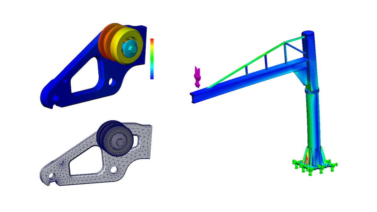
Another handy option is the adaptive mesh tool, available for linear static analysis. This function takes the task of mesh refinement completely under the guidance of the program, automatically re-running the study, refining the mesh where necessary until a pre-determined accuracy level has been reached. Here, the adaptive mesh has automatically added a large number of elements in high-stress regions such as the fillet and around the holes of this bracket.
The great thing here is that for a complex model, you can simply hit the Run button and walk away while the software does all the refinement for you. When you come back, you can see a detailed chart showing either a leveling off at the “real” stress values, or perhaps evidence confirming a stress singularity.
Below, we can see that after 5 loops, the adaptive mesher has achieved its required accuracy, which in this case is 2% error. We are thus assured that the maximum stress of 500 psi in the fillet is in fact a reliable result, independent of mesh factors.
For a comprehensive description of the convergence process, some interesting background math, and all the available options for convergence tools in SolidWorks Simulation, Hawk Ridge Systems subscription customers can view the full SolidWorks Simulation Convergence Guide on Hawk Ridge Systems eSupport.


Ok, maybe too late… anyways:
You are basing your convergence analysis on Stress. Why not looking for a quantity more suitable, like Strain Energy? is it possible in SW? what’s your opinion?
Best Regards,
Alex
Great Share. Just one question. My result got the converge as per the criteria what I set for H-adpative. During H adaptive mesh software determines the mesh size in the critical region and automatically applied to respected area as per to achieve the convergence value.
Now at the end I want to include my mesh details for client in the report. where should I get that value. coz as per my knowledge the mesh size what I defined at the starting of my run will be available to me in my mesh settings only. There is no updatation of mesh value which is considered to achieve the convergence. So just want to know is there a way to get the mesh size applied any where…?
Hi, I enjoyed the article.
A quick question: if after running the h-adaptive mesh and finding that the Von-Mises stress is diverging and not reaching a steady value, where exactly do you go from there?
Do you then revert back to manual techniques of neglecting the suspected high-spots and meshing in the regions you believe to be under high stresses (from engineering judgement)? Or can you look at the stresses close to – maybe a few elements away – from the singularity.
It’s been confusing me up to now. Any advice would be great.
Regards.
Hi Ross,
If the Von-Mises stress is diverging as the mesh is refined, that is likely the sign of stress singularities in the model. Since this article was written, a new tool was added to SOLIDWORKS Simulation called “Stress Hot Spot Diagnostics” which can alert you to these areas- generally any element with a node on the edge where the singularity is located will be invalid, but the next element away from that will give a valid result. You can either look at these elements some distance away or try to remove the source of the singularity (i.e. adding a fillet to the edge, or moving the location of a fixture).
Building on the last point, reading the stress at the elements neighboring the singularity region, it’s well in excess of the material’s yield point, however I’m using a linear solver meaning it won’t give realistic answers anyway. In this case, is it generally better to simply say “the material will almost certainly fail” OR “neglect it and simply try to find the maximum stress in the linear region that converges to a constant value”?
If the latter is not a viable solution then logic says that a non-linear solver would be necessary but again, I am not 100%.
if we have maximum stress at any point in assembly what should we do
Thank you
Hi Damon.
I have a shaft with bearing fixtures and 1 force load, with apparently no hot spots and my results never converge in the one spot. I tried to put huge fillets, I tried with h-adaptive meshing….
What can I do? What can I research for solving this?
My SW is 2016 so I do not have the “Stress Hot Spot Diagnostics”
thank you in advance
Alex,
Great question. You’re correct that in my example of manually checking convergence using the Trend Tracker, we are looking at maximum Von Mises stress in the model which is not the best predictor of error. However, it is possible to check other results such as Strain Energy. In fact, the automatic adaptive meshing which I also mentioned in the article does just that; the h-adaptive mesh checks the strain energy normalized error. An accuracy setting of 98% means that the mesh refinement will continue until the RMS strain energy norm error is less than 2% for the entire model.
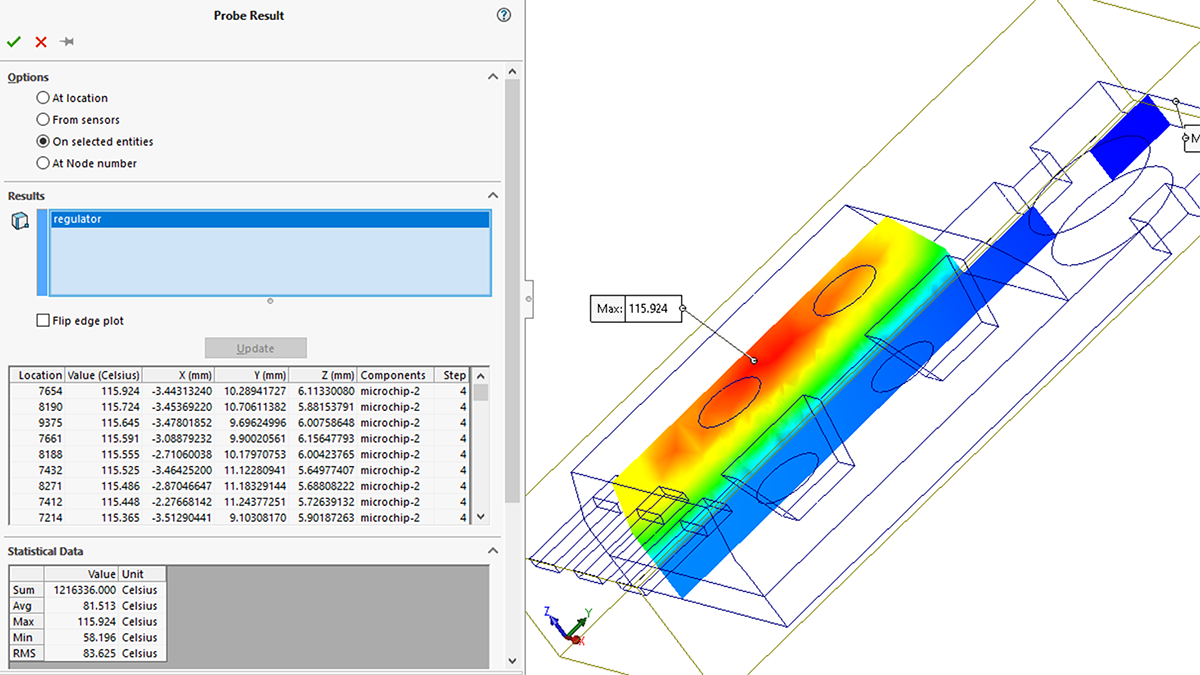
You can check the strain error yourself by right-clicking Results, Define Stress Plot, and choosing ERR: Energy Norm Error. You can even check the RMS value (as the adaptive mesh does) by using the Probe tool, choosing On Selected Entities, and selecting the solid body of the part(s) in question. For further information, please refer to our SolidWorks Simulation Convergence Guide on Hawk Ridge Systems’ eSupport site.
Hey Alex – Strain Energy could certainly be tracked and converged in SolidWorks Simulation – and Strain Energy error is the parameter that is tracked by the background by the adaptive meshing tool.
Hi Devi,
You can certainly view the mesh properties after h-adaptive refinement. If you right-click on the Mesh folder in the study tree, you can choose Mesh Details. This will show you the number of elements and nodes, the maximum aspect ratio, etc. This information is also included in a report as long as you make sure the ‘Mesh Information” box is checked when the Report Options screen appears.
If you’re looking for more data about the mesh, you can also create mesh plots (right-click the Mesh folder, Create Mesh Plot). These allow you to simply view the mesh, or plot the aspect ratio or Jacobian of the mesh. You can view information about individual elements by right-clicking on one of these plots and choosing “Probe and List Selected.”
Thanks for the response.
I am actually using an older version hence I don’t have the ‘hot spot’ feature. However what I have been doing is using h-adaptive mesh refinement, which basically shows that there is a singularity. I’ve then used ISO clipping to identify any stresses that are beyond the allowable limit. Since some of these stresses are present a number of elements (up to 8 elements) away from the singularity, would you agree that this confirms that they are genuine? And, if so, to identify a true maximum stress, would you say I’d need to then refine the mesh in this region until convergence is achieved?
Thanks again.
Hi Ross,
If you are looking at mesh elements that are away from the location of the singularity (i.e. an edge) then yes, those values are reliable. I would say 2+ elements away is a safe bet.
As far as identifying a true maximum stress, that value is most likely going to be at the location of the singularity itself (i.e. the edge) which means it will be impossible to find the true value even with additional mesh refinement, whether you’re using h-adaptive or not. The only way to find the true maximum stress would be to eliminate the singularity, such as by replacing the edge with a fillet.
Hi Ross,
As you noted, a linear study assumes a linear elastic material model which means that it cannot predict what will happen to the material after the yield point. If you see results above the yield stress in such a study, the only conclusion you can draw is that the material would yield in that area. If you wanted to predict the post-yield behavior, such as how much permanent deformation there would be or if the ultimate strain is exceeded, you would need to run a nonlinear analysis with the appropriate plasticity material model. These capabilities are available in SOLIDWORKS Simulation Premium or SIMULIA Abaqus.
Thanks for the response, I appreciate the advice.
Hi Awais- this article covers some methods to help determine if the stress value you are looking at is real (such as refining the mesh). If it is, you’ll want to evaluate the success/failure of your design based on that result.
Hi Pablo,
Even in the cases of stress singularities like this article discusses, even though you may not achieve results convergence, the location of the singularity should not repeatedly move. There may be two or three different singularities in the same model, but their location is not random- it’s based on the factors described above such as sharp corners or fixtures. I’d suggest a finer starting point before applying h-adaptive mesh, or perhaps try p-adaptive meshing instead. If you still see the behavior I’d suggest contacting your local reseller to see if you’re encountering a software issue from 2016 that has since been resolved.