A good design idea isn’t worth a thing if the end product isn’t strong enough. A SOLIDWORKS Simulation study allows us to understand how a design will respond to real life forces before it hits the production floor. Conducting a proper finite element analysis of a part can drastically cut down on prototyping time and provide design validation or justification for changes. The most common indication of this is a von Mises Stress value. In this article, we will review exactly what Stress is (engineering-wise, that is) and how a von Mises value takes the stress out of, well, stress.
One of the criteria we often use to verify part design is Stress. If we want to make sure a part doesn’t break under a given load, we need to ensure that the maximum stress in the part is below the yield strength of the material. But what does that even mean? How does SOLIDWORKS measure the stress in the part? And how can a simple comparison of stress values verify that the part isn’t failing? Let’s break it down.
What Is Stress?
Stress is simply a measurement of the internal forces in a body, as a result of externally applied loads. The units of stress are the same as those of pressure: force per unit area (psi, since you’re likely working in English units). As a result, we can roughly calculate a stress value by dividing the total force by the cross-sectional area.
Let’s make things a little more complicated.
Force is a vector – it has both magnitude and direction. As a result, stress has direction as well. So, what happens when you have complex (multi-directional) loading? Your stress inside your part will have components in each of these different directions. As an example, assume you have a part centered at the origin. If you pull on it only in the direction of the X-axis, it will only have stress values normal to that direction. However, if you also pull on it in the Y-direction as well, it has stress normal to X from the original force, but also stress normal to Y from the Y-direction force. In addition to normal forces you also must consider shear stresses. If normal stress is trying to stretch a part or compress a part, then shear stress is trying to twist a part or slice a part. These stresses all play a part in evaluating failure using SOLIDWORKS Simulation results.
To depict the different stresses that can be experienced by a part, look at the 3D cube below. We can have up to three different stress normal directions, as well as up to three different shear directions (X on Y, Y on Z, and X on Z). This means we can in theory have six different stress values. That’s a lot to try to calculate or interpret!
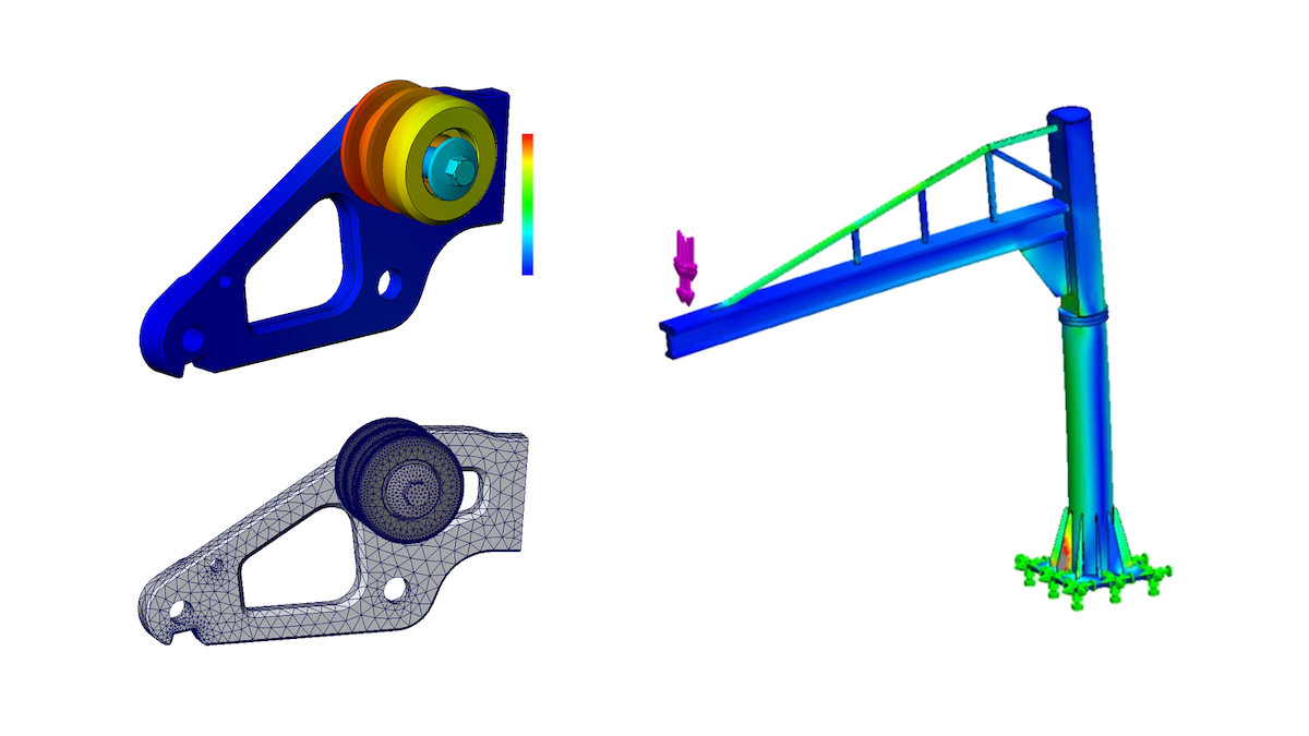
Each of these stresses can be solved for based on the loading conditions. This is where the heavy math comes in. Luckily for us, SOLIDWORKS takes care of all those tricky computations for you. It’s truly incredible how SOLIDWORKS runs through thousands of iterations of those calculations, and all in just a few minutes or even seconds. SOLIDWORKS displays the six different stress values using stress plots when it finishes a simulation. These plots only tell us part of the story, though, because all of them contribute to whether the part will yield or not.
We know the strength of a given material in terms of stress. In many cases it’s listed as a single value: yield strength. For example, our material properties list the yield strength of AISI 1020 steel as 51,000 psi. This means that, at that stress value, our material will begin to yield, which is the first step toward part failure. However, we cannot simply compare each normal direction or each shear to the yield value and know for certain that the part won’t fail. This is where our problem arises: how do we compare stress values in scenarios of complex loading?
Our engineering team has simulation experts that would be happy to answer questions like these and help you discover how to make the most of your SOLIDWORKS software. Contact us at Hawk Ridge Systems and our engineering gurus will be ready to assist. Thanks for reading!


